Gregorian telescope building log
This page describes the process of building the telescope itself. For the making of the mirror set, go to the mirror making page.
A bit of design
The design overview of the realized telescope:

The two finished mirrors turned out with the following parameters:
- Primary: D=149mm, RoC=848mm, F=424mm, k=-0.86
- Secondary: D=37mm, RoC=174mm, F1=98, F2=792, k=-0.62
The primary mirror is made out of 19mm floatglass and cored with a 40mm hole. The weight of the finished primary is around 750 grams.
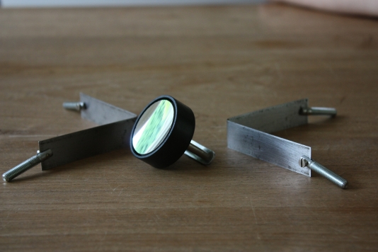
The secondary is made out of 8mm floatglass, which leaves about 5mm in the center after it is done. It will therefore be very light-weight at only 17 grams. This low secondary weight is actually required to minimize vibrations. The image stability of this Gregorian design with its large secondary magnification is quite sensitive to vibration.

With the mirrors that came out of the grinding process, the above spot diagram results. It is a lot worse than designed, caused by a figuring error. The primary correction should have been -0.99 instead of -0.86.
The back focal length equals the long focus of the secondary. The optimum across the field of 24mm diameter is reached a fraction of a mm beyond the paraxial focus.
Tube
To see how these work out, I ordered a hard-paper tube from Gerd Neumann for the OTA. The dimensions are 180mm inner and 185mm outer diameter, length is to be defined. The tube is very rigid and yet weighs close to nothing. The material resembles what was used long ago as basis for electronic circuits. Painting can be done with common alkyd based paint, or car paint. I used an alkyd primer to make the surface even smoother than it already was.
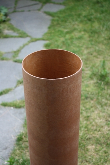
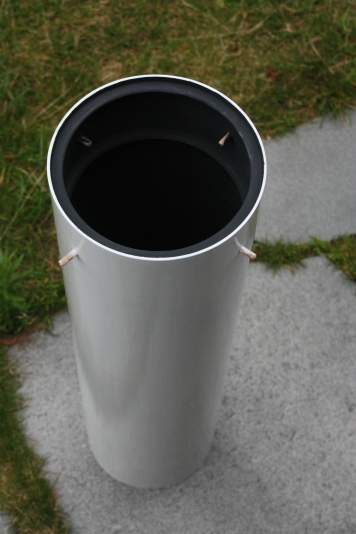
Left the unfinished tube material, right sanded primed and one layer of paint. The outer surface requires a bit mor sanding, and the inside needs a blacker paint. This one is supposed to be ultra matte charcoal black, but to my eye it really is grey.
Mirror cells
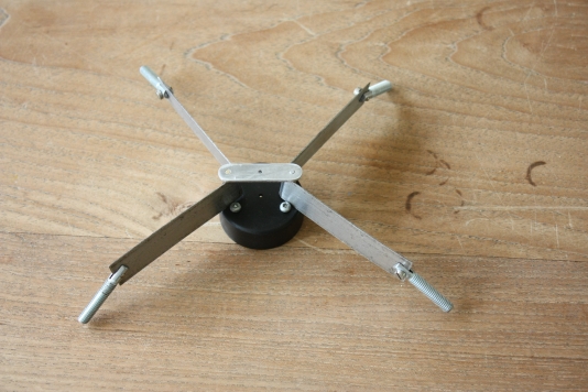
The secondary cell and spider is based on a 40mm PVC end-cap. In this cap an aluminium disk rests on a single steel ball from a bearing, which serves as pivot, three screws enable collimation. The secondary mirror is glued on the aluminium disk with clear silicone kit.
The spider is suspended in the tube by means of two V-shaped steel bands, bent around two off-center axes. The suspension must be very rigid, because (at F/24) any movement will have great effect in the focal plane.
The cell for the primary is a bit more complicated, it is built up from three ply disks. The lower two are fixed to the tube and form the bottom, the third disk carries the mirror support and moves snugly up and down in the tube. Three spring-loaded adjustment screws enable the mirror to be moved for collimation. Unlike shown in teh photo, the springs protrude through the upper bottom disk, so compression takes place inside the bottom and hence the construction height is minimized.


On the carrier disk the actual primary cell is mounted, made of an aluminium disk and three ball-bearings. Three aluminium brackets serve as spacer and to keep the mirror centered. On the baffle tube a retaining ring is fit that holds the mirror down. Possibly som additional felt is needed on the baffletube, to better center the primary. In any case, to prevent any strain the mirror will not be glued to the cell.