A Corrected Dall-Kirkham telescope
This is a telescope type I've had on my wish list for some time. The convex secondary is not hard to make, since it is spherical. The fast primary is also quite doable, also because it only needs to be corrected partially, it is an ellipsoid with a conic around -0.6. The variant with a corrector lens (CDK) is also fairly compact, considering aperture and system focal length.
When you plan to build a Dall-Kirkham telescope, there are basically two options:
- Make a slow, long focus system to avoid the need for correction. A commercial example is the Gladius CF315.
- Make a shorter focus system, which requires a corrector to compensate for the excessive off-axis coma. An example of such system is CDK14 made by PlaneWave instruments.
The Corrected Dall-Kirkham is however a feasible alternative, avoiding the need to grind specific lenses, when the corrector lens can be based on off the shelf lenses. This CDK design is further worked out on this page, and a building log can be found here. The mirror grinding log can be found here.
Overview
The design parameters are as follows:
- Primary: 300mm, RoC=1800mm (F/3), k=-0.69
- Secondary: 106mm, RoC=-925mm, k=0
- System: f=2525mm, FoV=22mm (0.5°)
- Mirror separation: 603mm,
- Secondary to corrector: appr. 616mm
- Focal plane is ~230mm behind primary vertex

Due to the small mirror separation, the overall tube length can be kept within 75cm, which is quite small for a 300mm F/8 instrument. The field is well corrected (Strehl<95%) over more than 0.5° or 20mm, in fact it is vignetting-limited by the size of the corrector lenses.
A point of atention is the correction of the primary, which should be close to -0.69. Since this is elipsoid, a null-test could in principle be used to qualify it, but alas the long focus is some 10m away. Instead the mirror will be etsted using an interferometer. The secondary is convex spherical, and can be fringe-tested against a reference sphere.
Performance
The performance of this system is outstanding. The field is well withing diffraction limit to more than 0.5°.

The locations of the optics are fairly touchy, but the optics themselves can vary quite a lot and still enable a good solution. For example, the initial design RoC of the secondary was 950mm, now it is 925mm and the solution is as good.
Tolerances
Since I plan to build this system without advanced machine tooling, it is worth to have a closer look at the tolerances in the optical design. This analysis will indicate the points in the mechanical design that require extra attention. Since the secondary is spherical, its placement is not very critical as long as there is good tilt adjustment. This is a big advantage of the Dall Kirkham system. However, the location and tilt tolerance of the corrector is more critical and needs to be quantified.
Above example spotdiagrams with effects of corrector deplacement and tilt are shown.
When considering alignment of the optical train it is also important to have an idea of the tolerances. To make mechanical design easier, the corrector is fixed to the bottom of the OTA, like the focuser. This leaves adjustments of primary and secondary, where the secondary only needs tilt adjustment since it is spherical. The primary however requires all 6 DOF, i.e. lateral and axial position as well as tilt.

The effect of distances on Strehl value is shown in the two graphs:


Two parameters are considered here, the primary to secondary and the secondary to corrector separation. The Strehl is given for spots on axis and at the edge of the field (0.25°). The ideal value is where the peaks coincide, i.e. best over the complete field of view. Especially the values at the edge drop rapidly. Ideal for this system is primary-secondary distance of 603.5mm, and a scondary-corrector separation of 615mm, corresponding nicely with optimum calculated with OSLO.
For the corrector tilt, a much more critical picture follows:

The limit is about 0.1° when all other values are ideal. Corrector offset is less critical, but should still be within 0.5mm or so.
Mechanical design
Initially a 2-D drawing was made with the general idea for the construction:

Now I have a 3-D printer, which opens up a whole new class of solutions. The consequence however is that also a 3-D CAD program was needed, and I settled for FreeCAD.

The 3-D image shows a worked-open system. The idea is to make a very light weight construction with a wall made from 1.5mm airplane grade triplex. This material has about the same Thermal Expansion coefficient as borosilicate glass (Pyrex). The construction is rigged with rings of birch multiplex and has a built-in Losmandy size (75mm) mounting rail. The goal is to keep the total weight under about 10kg, so the NEQ-6 has no problems to carry it.
And of course: some of the harder parts, such as levers and baffle tubes, will be 3-D printed.
Primary mirror assembly
The primary assembly on the bottom side of the OTA:

It consists of a cell, which allows alignment in 5 degrees of freedom, 3x translation and 2x tip/tilt. The corrector is mounted into the focuser base to auto-align it with the eyepiece. The baffle tube is part of the mirror cell, and hence moves with the primary. The mirror is secured with a full ring instead of clips. The ring is connected to the primary cell base.
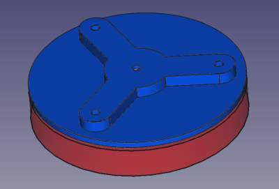
Primary cell.

 |
The mirror cell will be a basic 6 points flotation type, which adds about RMS λ/125 to the wavefront error (P-V λ/25). The support point are at 65% of the mirror radius. The 3 axial levers use a pair of bearings as fulcrum, and another pair for support points. The localization of the levers will be done wit a very thin plastic sheet, glued to the central axis of each lever and to the cell hub. The levers themselves will be printed with PETG. The cell basis will rest on three push screws, which support the base under the center of the axial levers, allowing adjustment of tilt and axial position. This localisation minimizes torsional effects in the cell base on the axial lever positioning. Lateral alignment is done with three screws pushing on the side flanges of the cell base. Finally, three locking bolts are added to fix the cell base when alignment is done. Lateral support is provided by the central primary cell hub. Lateral support needs to be all around because the telescope will be equatorially mounted. A ring is mounted on top of the three lateral lever fulcrums. This ring is overhanging the primary by about 1mm, effectively preventing it from falling out of the cell. |
Corrector.
 |
The corrector cell, based on a ThorLabs LM2-A lens holder, is mounted directly on top of a 3D printed insert for the focuser base. The location relative to the focal plane therefore is fixed. Care must be taken during construction to not introduce too large errors, but a couple of remaining mm can be adjusted with the secondary. |
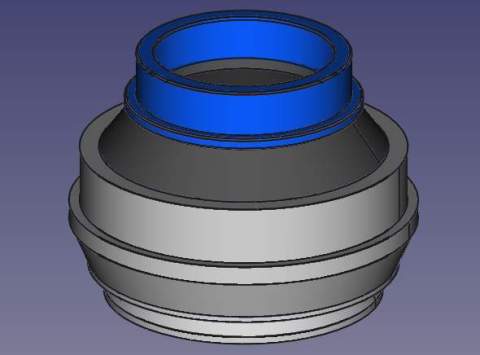
Secondary mirror assembly

The secondary cell is 3D printed. The secondary glues to a baseplate which can rotate about a central ball bearing. The ball rests on the secondary holder plate and tip-tilt adjustment is done with three screws. Axial adjustment has to be done by choosing the proper ball size, and should be about a mm or so within design criteria. The remaining axial fine alignment is done by adapting the primary-secondary distance with the primary cell.