RA axis drive
To drive the RA axis of my new fork mount, I needed another stepper motor control. The design is based on the Vixen polaris prototype, but now a decent PCB was created for it. Also, there are some controls to accellerate or decelerate the drive rate, in order to center an object. In principle this interface can also be used for guiding. The driver also has a terminal interface over 3-wire RS232. This terminal is used to adjust the default stepper speed and direction. The settings are stored persistently, and hence the device can be tuned for almost any mount.
Electronics
As in the prototype, the circuit is built around a PIC 16F628 and a ULN2004 aray of TTL-Darlington drivers. The software timing is controlled by the 20MHz crystal clock, and can accurately time the stepper pulses.
The RS232 interface is now fully functional and three discrete I/O pins are used to control a LED and to enable speed control.
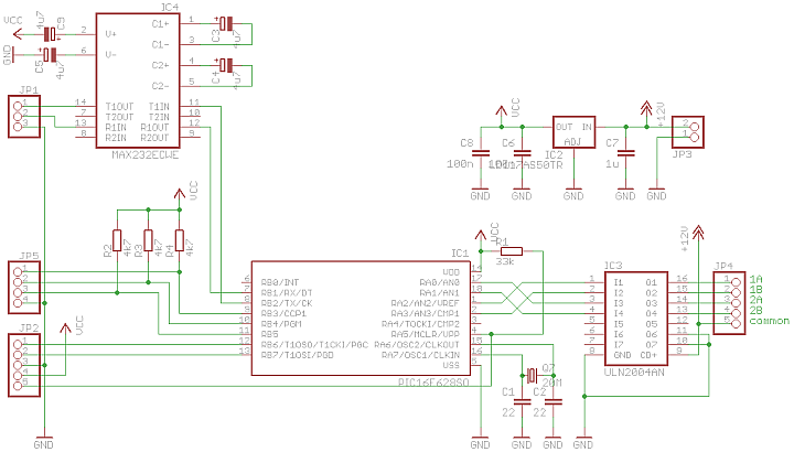
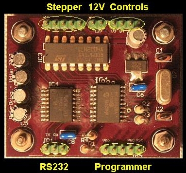
A decent 43x53mm PCB has been layed out and produced by OSH-Park. The meaning of the pinheader connectors are indicated in the image, signals are (partly) on the PCB:

The controls are best connected with the RC network shown below, to dampen the glitches when operating the switches. The remaining spikes are filtered out in software, by a debounce algorithm. This results in a very consistent behaviour of the controls.

Software
The software is quite straightforward. It has been built with the HiTech C compiler and MPLAB 7.50, later versions do not work with the ICD-2 programming device.
The main routine is a loop which waits for input over the RS232 interface. Whenever a linefeed is detected teh received string is parsed and processed. Two commands are accepted, one to set the number of ticks between half-steps and the other to set stepping direction. Otherwise a simple help is dumped on the terminal screen.
Each tick is 100usec, so this is basically the accuracy of the step interval timer. Minimum setting is 10 (1msec), maximum 10000 (1sec). The command is: m<nr>, where nr indicates the number of 100usec ticks.
The other command is to set the direction in forward or reverse: d{f|r}.
Both settings are immediately stored in EEPROM, so normally connecting a terminal is a one time action. After this the driver will power up with the entered settings. For this reason it is not really neccessary to have a real RS232 connector on the casing.
The other important part of the software is an Interrupt Service Routine (ISR), that serves the RS232 interface and (most importantly) handles the 100usec timeouts. It is the ISR that moves the stepper to its next state each time when the step interval counter reaches 0. The timer itself is repetitive, with the reload implemented in hardware. Therefore it is very accurately coupled to the 20MHz crystal frequency (i.e. 2000 clock cycles).
The required step interval can be deduced from the fact that each (sidereal) second the RA axis needs to rotate 15 arcseconds. A 200 step per revolution unipolar stepper will do 400 half steps per revolution. Knowing the reduction factor of the gearing, the number of half steps per second and from that the inter-step interval can be derived. This gives the number to be entered with the connected terminal.
As an example, the gearing of my mount reduces the speed with a factor 3080. So instead of 15" per second, the stepper rotates at 12°50' per second. Since each half step is (360/400)°, the moter speed should be 14.26 halfsteps per second, or 0.0701 second between each halfstep. So this means that the number of 100usec ticks between each halfstep is 701, which is the number to be added to the m command: m701.
Result
Eagle file and software are available on request.